
 Tel:+86-575 -87957662
 Email:
 English
 中文简体
中文简体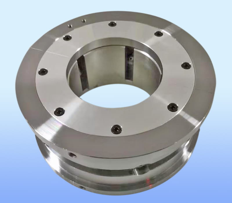
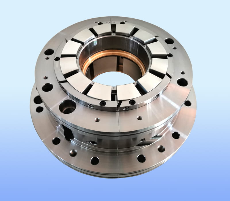
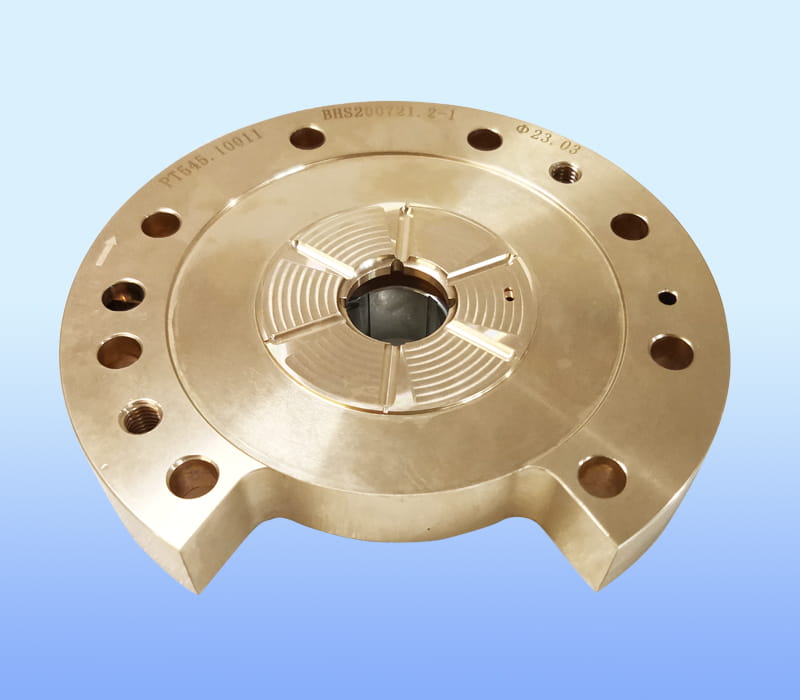
ZHEJIANG BHS JOURNAL BEARING CO.,LTD. located in FengXian District of ZheJiang, the company's brand "BHS", is a professional tilting pad thrust bearings manufacturers and Tilting pad bearings factory...

Rotating equipment such as turbines, compressors, and pumps depends heavily on how the rotor is supported inside the machine casing. The bearing type chosen directly affects rotor stability, vibration behavior, and the maximum speed the machine can safely reach. Two broad categories dominate industrial rotating machinery: fixed geometry bearings, where the bearing surface is a single rigid arc, and tilting pad bearings, where the load-bearing surface is divided into several independently movable pads.
This distinction is not a minor design detail. It changes how the oil film behaves under load, how the rotor responds to disturbances, and how much clearance engineers must build into the design to avoid instability. Understanding these differences helps engineers select the correct bearing type when specifying new equipment or troubleshooting recurring vibration problems.
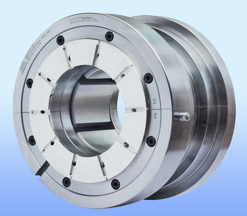
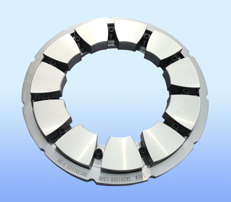
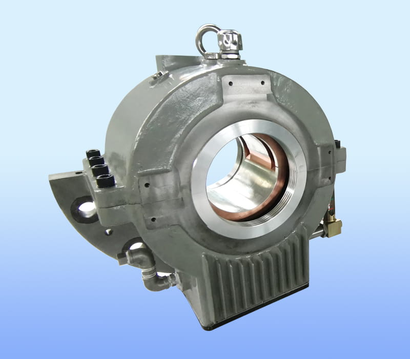
A tilting pad bearing replaces the single continuous bore of a fixed bearing with a set of individual pads arranged around the shaft. Each pad rests on a pivot point and can rock slightly in response to the forces generated by the rotating shaft. This pivoting action allows each pad to form its own converging oil wedge, independent of the others.
The design appears in two primary configurations depending on the direction of the load being supported.
Supports radial loads perpendicular to the shaft axis. Multiple pads surround the shaft, each generating a localized hydrodynamic film that reacts to shaft position in real time.
Supports axial loads along the shaft axis. Pads are arranged in a circular pattern facing the thrust collar, each tilting to maintain an optimal oil film thickness as load and speed change.
The operating principle relies on hydrodynamic lubrication, the same physical phenomenon that governs any fluid film bearing. As the shaft rotates, it drags oil into a narrowing gap between itself and the bearing surface, generating pressure that lifts and centers the shaft without metal to metal contact.
In a fixed bearing, this wedge forms along a single fixed arc, meaning the pressure distribution is dictated entirely by the bore geometry. In a tilting pad journal bearing, each pad adjusts its own angle to the shaft surface based on the local film pressure, so the wedge shape is self-optimizing at every pad location and at every operating condition.
Because each pad reacts independently, a tilting pad bearing effectively behaves like several small bearings working together, rather than one continuous rigid surface.
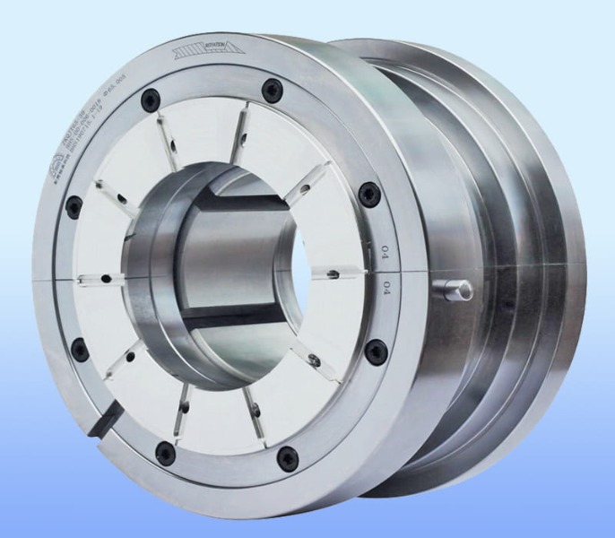
The diagram below illustrates how a fixed bearing forms a single continuous oil wedge compared to how a tilting pad bearing forms multiple independent wedges around the shaft.
Fixed bearings work well in many general purpose applications, but as rotor speed increases, they become prone to a self-excited vibration phenomenon commonly known as oil whirl, and at higher severity, oil whip. This instability occurs because the oil film in a fixed bearing can develop a cross-coupled stiffness that feeds energy into the rotor motion rather than damping it.
Tilting pad bearings largely eliminate this cross-coupling effect. Because each pad is free to pivot, it cannot transmit a sustained tangential force back into the shaft the way a rigid bore can. This is the primary reason tilting pad journal bearings are the default choice for high speed turbomachinery.
| Characteristic | Fixed Bearing | Tilting Pad Bearing |
|---|---|---|
| Oil film stability at high speed | Prone to oil whirl above certain speed thresholds | Inherently more stable due to independent pad response |
| Cross-coupled stiffness | Present and can drive instability | Minimal, since pads cannot sustain tangential coupling |
| Mechanical complexity | Simple, fewer moving parts | More complex, requires pivots and individual pads |
| Load capacity per unit area | Moderate | Comparable or higher, depending on pad count and design |
| Typical application range | General purpose pumps and fans | Turbines, compressors, high speed pumps |
| Maintenance and inspection | Simpler to inspect and replace | Requires attention to pivot wear and pad alignment |
Axial loads in rotating machinery arise from pressure differentials across impellers, helical gear forces, or the weight of a vertically oriented rotor. A tilting pad thrust bearing addresses these loads with the same self-aligning principle applied to journal bearings, but oriented to resist motion along the shaft axis.
Each thrust pad tilts to form a converging film between itself and the rotating thrust collar. Because the pads can adjust independently, the load distribution across the full ring of pads tends to be more even than what a fixed thrust surface can achieve, particularly when the collar is not perfectly perpendicular to the shaft due to manufacturing tolerances or thermal growth.
| Equipment Type | Typical Axial Load Source |
|---|---|
| Centrifugal compressors | Pressure differential across impeller stages |
| Steam and gas turbines | Blade reaction forces and thermal expansion |
| Vertical pumps | Weight of rotating assembly plus hydraulic thrust |
| Gearboxes with helical gearing | Axial component generated by gear tooth angle |
Vibration in rotating equipment often originates from the interaction between rotor dynamics and bearing stiffness and damping properties. A tilting pad journal bearing reduces vibration through several interconnected mechanisms rather than a single feature.
Because the pads distribute the load response around the full circumference rather than concentrating reaction forces at one arc, the overall stiffness and damping presented to the rotor becomes more uniform in every direction. This uniformity is one of the main reasons vibration amplitudes measured on machines with tilting pad bearings tend to remain flatter across a wider speed range compared to machines with fixed bearings, where amplitude peaks can appear sharply near certain critical speeds.
Field data collected across various high speed compressor trains has shown that converting from fixed bearings to tilting pad bearings during a rotor dynamics redesign can reduce vibration amplitude at the first critical speed by a substantial margin, often bringing readings well within standard acceptance criteria where the original fixed bearing design had marginal or failing values.
Yes. High speed capability is one of the primary reasons this bearing type exists. The relevant parameter engineers track is the product of shaft surface speed and bearing diameter, often expressed as a DN value. Fixed bearings tend to reach their stability limit at lower DN values because the whirl threshold speed is a direct function of bearing geometry and clearance.
Tilting pad bearings push this threshold significantly higher because the whirl-inducing cross-coupled stiffness term is largely removed from the system. This is why tilting pad journal bearings are standard equipment in applications such as steam turbines, gas turbine generator sets, high speed centrifugal compressors, and multistage pumps operating well above the speed ranges where fixed bearings remain stable.
Not every machine requires a tilting pad bearing. Selection should be based on operating conditions rather than assuming the more complex design is always the better choice.
Operating speed stays well below the stability threshold, load direction is constant, and the application tolerates simpler maintenance with fewer precision components.
The machine operates at high relative speed, experiences variable or light loading, or has previously shown vibration instability that correlates with a whirl frequency near half of running speed.
When a machine equipped with tilting pad bearings develops vibration or thermal issues, the root cause is often related to pad condition, lubrication supply, or alignment rather than the fundamental bearing design.
| Symptom | Likely Cause |
|---|---|
| Elevated bearing temperature | Insufficient oil flow or degraded lubricant viscosity |
| Subsynchronous vibration component | Pad pivot wear reducing the self-aligning response |
| Uneven pad wear pattern | Shaft misalignment or unequal load distribution |
| Sudden vibration increase at startup | Insufficient oil film during low speed operation |
Routine monitoring of bearing metal temperature and vibration spectra remains the most reliable way to catch developing pad wear before it progresses to a functional failure.
Tilting pad bearings are hydrodynamic bearings made of several independent pads that pivot to form self-adjusting oil films, used to support radial or axial loads in rotating equipment.
Each pad pivots in response to local oil film pressure, allowing it to form an optimal converging wedge as shaft speed and load change, which keeps the shaft centered without metal to metal contact.
They largely eliminate the cross-coupled stiffness that causes oil whirl and oil whip in fixed bearings, allowing machines to run stably at much higher speeds.
By distributing load response evenly around the shaft and minimizing cross-coupling forces, they produce more uniform stiffness and damping, which flattens vibration response across the operating speed range.
Yes, they are specifically designed for high speed applications and are standard in turbines, compressors, and high speed pumps where fixed bearings would become unstable.

ZHEJIANG BHS JOURNAL BEARING CO.,LTD. located in FengXian District of ZheJiang, the company's brand "BHS", is a professional tilting pad thrust bearings manufacturers and Tilting pad bearings factory...
Copyright © 2017 ZHEJIANG BHS JOURNAL BEARING CO.,LTD. All Right Reserved. China Tilting Pad Journal Bearings Manufacturers
