
 Tel:+86-575 -87957662
 Email:
 English
 中文简体
中文简体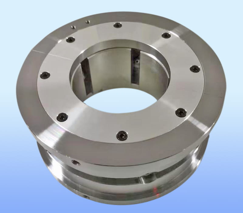
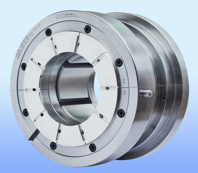
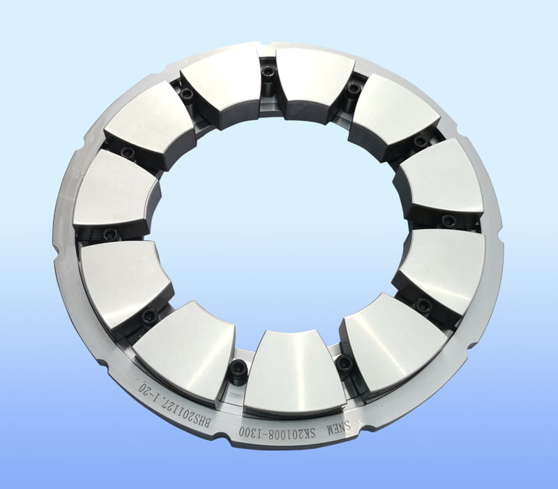
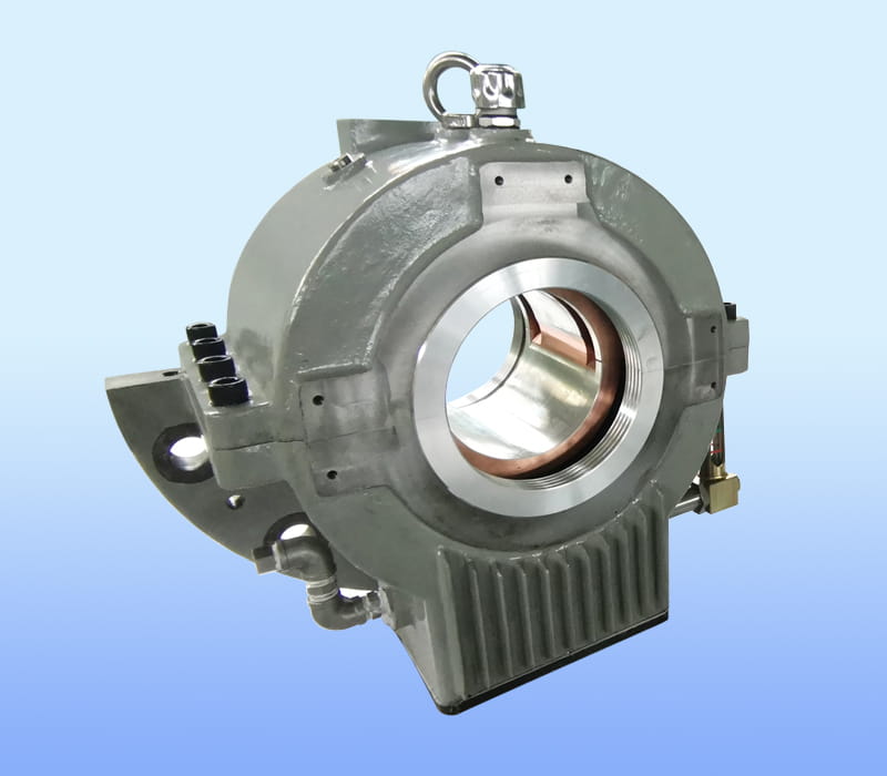
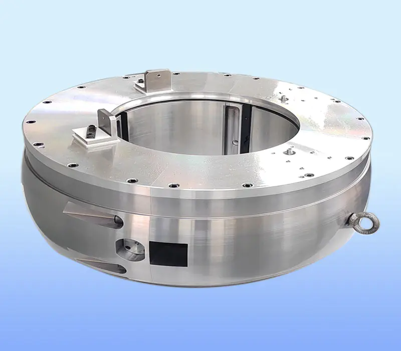
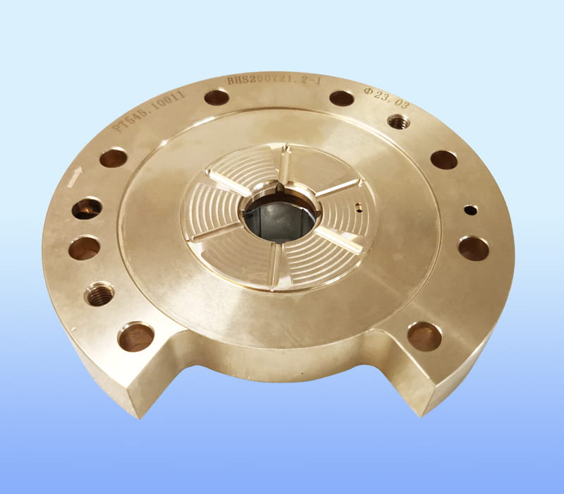
ZHEJIANG BHS JOURNAL BEARING CO.,LTD. located in FengXian District of ZheJiang, the company's brand "BHS", is a professional tilting pad thrust bearings manufacturers and Tilting pad bearings factory...

The gas turbine impeller stands at the heart of every modern power generation system. Its aerodynamic and structural integrity directly dictates overall cycle efficiency, fuel consumption, and maintenance intervals. For engineers and procurement specialists, selecting the right impeller involves navigating a complex landscape of materials, manufacturing precision, design trade-offs, and operational duty cycles. This guide provides a structured, technically grounded framework to support that decision-making process. By examining material science, advanced manufacturing techniques, innovative aerodynamic configurations, and real-world failure mechanisms, we equip you with the actionable criteria needed to optimize performance and total cost of ownership for your specific application.
In a gas turbine engine, the compressor section relies on the impeller to perform the critical function of accelerating and pressurizing incoming air before it enters the combustor. As the impeller rotates at high speed, air enters axially through the inducer region and is turned radially outward by the curved blades. This redirection, governed by the principles of angular momentum, imparts kinetic energy to the air. The diffuser downstream then converts this kinetic energy into static pressure rise. The impeller's aerodynamic design — including blade angles, passage curvature, and tip clearance — determines the pressure ratio and efficiency of the entire compressor stage. Key geometric features include the inducer (entry), exducer (exit), and the blade profiles that define the flow path.
Material choice is the single most consequential decision in gas turbine impeller design, as it governs temperature capability, creep resistance, low-cycle and high-cycle fatigue strength, and corrosion resistance. The operating environment — with inlet temperatures often exceeding 1000°C in advanced turbines — demands alloys that maintain structural integrity under extreme centrifugal loads and thermal gradients.
Data from a NASA-funded study indicated that lightweight impeller materials (specifically titanium aluminides) improved cyclic life by up to 18% compared to conventional nickel alloys under identical thermal-mechanical loading spectra, due to reduced centrifugal stresses and improved damping characteristics. Cost, however, remains a strong differentiator: nickel alloys are approximately 2–3 times more expensive than titanium grades, yet offer superior oxidation resistance at elevated temperatures. Procurement specialists must balance initial capital expenditure against predicted maintenance cycles and replacement intervals.
Ti-6Al-4V: 450°C max,
σ_UT ~ 950 MPa
Inconel 718: 700°C,
σ_UT ~ 1240 MPa
Si₃N₄: 1200°C,
ρ ~ 3.2 g/cm³
The transition from material billet to finished impeller involves several processing routes, each with distinct implications for geometry, surface integrity, and cost. The three principal methods are casting (investment or directional solidification), forging (isothermal or conventional), and subtractive machining via five-axis CNC centers. For high-volume, small-to-medium impellers, investment casting offers near-net shape capability with good repeatability, though it may require post-cast heat treatment and HIP (hot isostatic pressing) to close porosity. For critical rotating components, forged microstructures deliver superior grain flow orientation and fatigue strength, but at higher material utilization costs.
Five-axis CNC machining remains the gold standard for achieving the tight tolerances required in modern compressor stages. The simultaneous interpolation of X, Y, Z, plus two rotational axes (typically A and C) allows the tool to maintain optimal contact angles with the complex curved blade surfaces. Key parameters such as tilt angle (to avoid tool collision) and lead angle (to match the blade surface inclination) must be precisely controlled. Typical profile tolerances for high-efficiency impellers are within ±0.025 mm, with surface roughness (Ra) below 1.6 μm. Verification methods include coordinate measuring machines (CMM), optical scanning, and blue-light fringe projection for full-field geometry inspection.
Recent advances in computational fluid dynamics (CFD) and additive manufacturing have unlocked novel impeller architectures that push the efficiency envelope beyond conventional radial designs. Two notable configurations are the back-swept (or backward-curved) impeller and the tandem (split-blade) impeller. The back-swept design features blades that curve opposite to the direction of rotation at the exducer, reducing slip factor and improving work input at off-design conditions. Experimental studies have demonstrated that back-swept impellers can deliver up to 4.61% higher isentropic efficiency compared to radial-tipped designs under part-load operation — a critical advantage in grid-stabilizing peaking plants that frequently cycle between 60% and 100% load.
Tandem impellers incorporate a secondary blade row within the same passage to better guide the flow and reduce boundary layer separation, particularly at high incidence angles. While this configuration generally improves pressure ratio and overall efficiency, it introduces additional losses due to increased wetted surface area and potential mixing of wakes from the primary and secondary blades. Designers must carefully optimize the axial offset and circumferential spacing between the blade rows to balance efficiency gain against exit flow distortion. The trend in modern high-pressure ratio compressors is toward hybrid solutions: back-swept primary blades combined with splitter vanes at the inducer, offering a compromise between peak efficiency and stall margin.
| Configuration | Efficiency Gain | Pressure Ratio | Best Application |
|---|---|---|---|
| Radial-tipped | Baseline | 4.2:1 | Base load, steady |
| Back-swept | +4.6% (off-design) | 4.5:1 | Peaking/cyclic |
| Tandem | +2.8% (peak) | 5.0:1 | High-pressure stages |
Despite rigorous design and manufacturing, gas turbine impellers are subjected to extreme conditions that inevitably lead to degradation over time. The primary failure mechanisms include high-cycle fatigue (HCF) induced by aerodynamic forcing from upstream wakes and downstream obstructions; low-cycle fatigue (LCF) resulting from thermal-mechanical cycling during start-ups and shutdowns; creep, particularly at the blade root and rim regions; and corrosion/oxidation from contaminated fuel or air. Stress concentrations at the blade fillet radius and the inducer leading edge are common initiation sites. A post-service inspection program should include dye penetrant or eddy current testing for surface cracks, dimensional checks of tip clearance and blade profile, and material microstructure evaluation via replication.
Maintenance strategies typically follow a risk-based approach: preventive (fixed intervals), predictive (condition-based using vibration monitoring or performance trending), or reactive (run-to-failure). For critical assets, predictive maintenance yields the highest availability and lowest lifecycle cost. Key repair techniques for damaged impellers include weld repair of cracks followed by heat treatment and re-machining, or replacement of individual blades in modular designs. However, the repair decision must consider the remaining life predicted by damage accumulation models. Establishing a partnership with a qualified repair facility that has certified welding procedures and NDT capabilities is essential. For operators facing frequent HCF issues, altering the operating speed or modifying the diffuser vane count can sometimes mitigate the resonant response.
The supplier landscape for gas turbine impeller components ranges from large integrated manufacturers to specialized machine shops and aftermarket repair houses. Evaluating a potential supplier requires a balanced assessment of technical capability, quality systems, commercial flexibility, and supply chain resilience. The most critical technical criterion is the supplier's demonstrated ability to maintain consistent geometric tolerances and surface integrity across high-volume production runs, as revealed by statistical process control (SPC) data. Look for certification to recognized quality standards (e.g., AS9100D, ISO 9001:2015) and, for aerospace-derived applications, NADCAP accreditation for special processes like heat treatment and NDT.
Capacity to handle complex geometries is another differentiator: suppliers with five-axis machining centers and in-house metrology labs typically deliver higher quality and shorter lead times. In the industrial gas turbine maintenance segment, operators that implemented structured supplier scorecards — weighting on-time delivery, rework rates, and engineering support — reported a 22% improvement in first-pass yield and a 14% reduction in turnaround time. When requesting quotes, provide clear technical specifications including material grade, drawing tolerances, and acceptance criteria. A site audit of the supplier's facility, focusing on tool management, calibration records, and operator training, is strongly recommended before awarding a long-term contract.
Under normal operating conditions with regular maintenance, a gas turbine impeller can last between 30,000 and 50,000 hours, equivalent to roughly 3 to 5 years of baseload service. Actual life depends heavily on operating temperature, transient cycles, and fuel cleanliness. In peaking applications with frequent starts, the lifespan may be reduced to 15,000–20,000 hours due to low-cycle fatigue accumulation.
An axial impeller (or rotor) moves air parallel to the axis of rotation and is typically used in multi-stage axial compressors. A centrifugal impeller accelerates air radially outward, achieving higher pressure rise per stage but with lower flow capacity. In gas turbines, the first compressor stages are often axial, while smaller turbines may use a single centrifugal stage for high pressure ratio.
Costs vary widely based on size, material, and complexity. A forged nickel-alloy impeller for a 100 MW class turbine can range from $80,000 to $250,000, while larger steam-turbine-grade impellers may exceed $400,000. Aftermarket refurbished parts typically cost 40–60% of new OEM equivalents, depending on repair scope.
Yes, most impellers are refurbishable through weld repair, re-contouring, and coating restoration. The decision is based on crack depth, material condition, and residual life analysis. Refurbishment is cost-effective and can restore up to 95% of original performance if performed by certified specialists with proper post-weld heat treatment and balancing.

ZHEJIANG BHS JOURNAL BEARING CO.,LTD. located in FengXian District of ZheJiang, the company's brand "BHS", is a professional tilting pad thrust bearings manufacturers and Tilting pad bearings factory...
Copyright © 2017 ZHEJIANG BHS JOURNAL BEARING CO.,LTD. All Right Reserved. China Tilting Pad Journal Bearings Manufacturers
