
 Tel:+86-575 -87957662
 Email:

 English
 中文简体
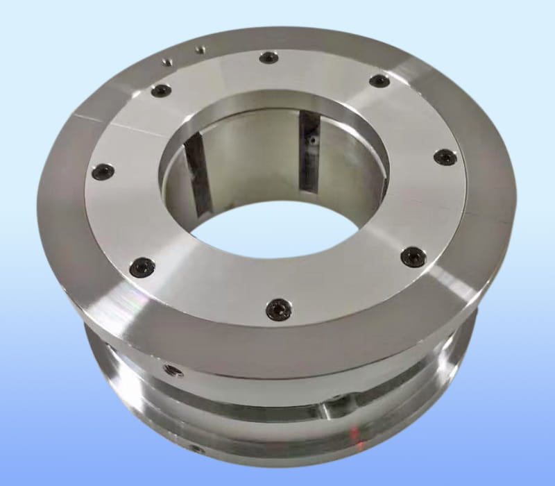
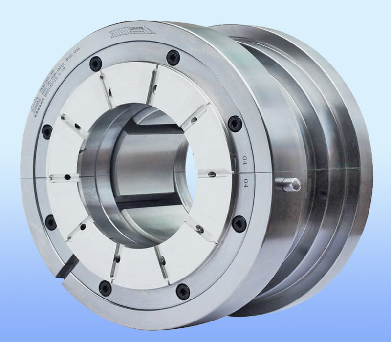
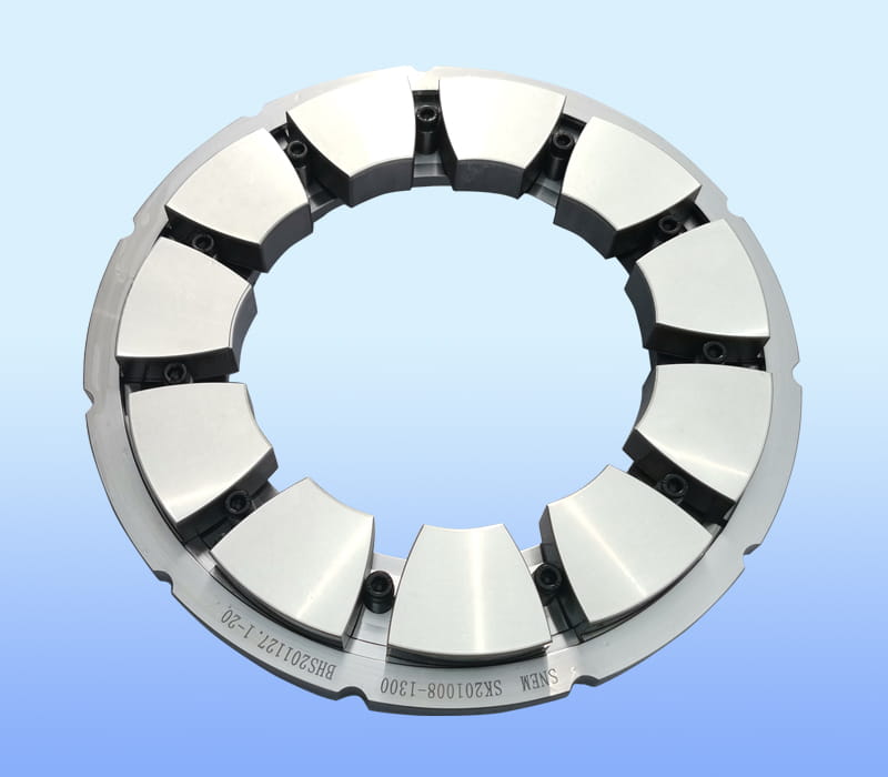
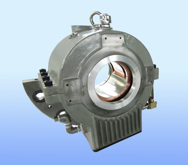
ZHEJIANG BHS JOURNAL BEARING CO.,LTD. located in FengXian District of ZheJiang, the company's brand "BHS", is a professional tilting pad thrust bearings manufacturers and Tilting pad bearings factory...

In rotating machinery, the impeller is the component that performs the actual work. It accelerates a fluid, guides its path and converts rotational energy into pressure and velocity. Small details such as blade curvature, hub fillet radius and passage smoothness determine how much input energy becomes useful output and how much is lost to turbulence, leakage and shock. For engineers working on aero-engines, industrial gas turbines and large centrifugal compressors, the impeller is an aerodynamic and structural component that must be designed as one system.
Operating requirements have pushed these parts in two directions at once. Machines are expected to run at higher rotational speeds and pressure ratios, while owners also want lower weight, longer service intervals and predictable behavior over tens of thousands of operating hours. A design that looks efficient on paper can still fail if its stress distribution, vibration response or manufacturing tolerances were not evaluated together.
Two
Main families of high-speed rotor construction
Five
Axes commonly used to machine complex blade surfaces
Zero
Joints in an integrally machined rotor root region
Efficiency, surge margin and mechanical life are linked. A modest improvement in blade surface quality or passage shape can change all three, so aerodynamic, material and manufacturing decisions should be reviewed together rather than in isolation.
Blades on a centrifugal impeller are usually curved backward or set radially, and the angles at the blade inlet and outlet decide how the flow is turned. Backward-curved blades generally offer a wider stable operating range and good efficiency, while radial blades are more robust and simpler to manufacture but require more careful control of slip. The designer balances these trade-offs against the required pressure rise and the allowable tip speed.
The passage between adjacent blades must expand gradually to prevent flow separation. Hub and shroud contours, leading-edge thickness and the axial length of the inducer all affect how smoothly the fluid enters the rotor. Local separation that begins at one blade can spread into rotating stall, which narrows the usable operating envelope and can cause vibration problems.
A blisk, or bladed disk, is a rotor in which the blades and disk are machined from a single forged or solid billet. This removes the root joints, fasteners and interface features common in assembled rotors. Assembled designs join separately made blades to a disk through dovetail roots or welded interfaces, or they attach a shroud to blades that were formed separately. Both approaches have a place, and the right choice depends on diameter, speed, repairability and production volume.
| Aspect | Integrally machined blisk | Assembled or welded design |
|---|---|---|
| Joint stress | No root joints, fewer stress concentrations | Joints need detailed stress analysis |
| Weight | Optimized by thinning webs and blades | Root and flange features add mass |
| Repair | Usually replaced as one unit | Individual blades may be replaced |
| Machining time | Long, because much material is removed | Shorter per part, more assembly steps |
| Typical use | High speed and high loading rotors | Large diameter or easily repaired units |
Integral rotors are attractive when the operating speed is high and the rotor must survive large centrifugal loads with minimal joint risk. Assembled rotors remain valuable where very large diameters make a single billet impractical, or where a field replacement of individual blades reduces downtime.
Material selection is governed by operating temperature, centrifugal stress, corrosion environment and density. Lower density reduces stress at the rim, while higher strength at elevated temperature allows thinner sections and lighter rotors. The table below summarizes typical limits, which depend strongly on heat treatment and exposure time.
| Material family | Typical service limit | Strength to weight | Machining note |
|---|---|---|---|
| Aluminum alloys | Up to about 200 C | Good at low temperature | Easy to machine, high cutting speed |
| Titanium alloys | Up to about 550 C | Excellent | Low thermal conductivity, needs careful cooling |
| Nickel-based superalloys | Up to about 700 C | Very high strength at temperature | Work hardens, demands sharp tools |
Aluminum alloys suit light compressors and process equipment operating at low and moderate temperatures. Their machinability allows short cycle times, and their low density helps reduce bearing loads. They are not appropriate where high temperature creep or aggressive heat exposure is expected.
Titanium offers a favorable balance of strength and mass for intermediate-temperature stages. Because its thermal conductivity is low, heat concentrates at the cutting edge, which calls for controlled feed rates, through-tool coolant where available, and attention to chip evacuation. Machining titanium also requires precautions against fire, since fine chips can ignite under poor practice.
Precipitation-hardened nickel-based superalloys are used where temperature and stress are both high, such as hot sections of gas turbines. They work-harden quickly, so tool geometry, cutting speed and tool wear monitoring must be managed closely. Surface integrity after machining is critical because micro-cracks or residual tensile stress can shorten fatigue life.
Manufacturing begins with a certified billet or forging whose internal soundness has been verified. Rough machining removes the bulk of the material, then finishing operations define the blade profile and hub transitions to final tolerance. Each stage leaves a controlled allowance for the next, which keeps residual stress and thermal distortion within limits.
Five-axis machines orient the tool to follow the blade surface continuously, reducing the number of setups and improving profile continuity between passages. Roughing removes most of the stock, semi-finishing leaves a uniform allowance, and finishing achieves tight profile tolerances. Short tool stick-out, adaptive toolpaths and controlled radial engagement help limit deflection and chatter on thin blades.
For some diameters and speeds, blades are formed separately and joined to a hub and shroud by welding or brazing. This route suits a welding impeller design, where weld quality, heat-affected zone control and post-weld stress relief become the main process risks. Weld inspection and dimensional checks after stress relief are essential.
A rotor that meets its drawing dimensions can still underperform if its surface finish, balance or internal integrity is poor. A complete inspection plan therefore combines geometric measurement, surface assessment, nondestructive testing and dynamic balancing, and it is documented with traceability to each billet.
| Feature | Typical control | Verification method |
|---|---|---|
| Blade profile | Plus or minus 0.05 mm on key sections | Coordinate measurement and scanning |
| Hub bore | Fine fit tolerance as per drawing | Bore gauge and CMM |
| Surface finish | Around 0.8 micrometers Ra on gas path | Profilometer |
| Balance | Grade set by speed and rotor mass | Balancing machine |
Inspection results are most useful when the plan is defined at the drawing stage. Specifying measurement points, datum schemes and acceptance criteria early avoids disputes later and shortens the approval cycle.
Rotating components with a common aerodynamic purpose appear in very different machines, and each application places its own demands on geometry, material and inspection.
Aero-engine compressor stages demand very low weight, high fatigue resistance and tight blade-to-casing clearances. Integrally machined rotors are common here because joint-free geometry supports high speed operation under heavy centrifugal loading.
Industrial gas turbines run for long periods at steady load, so creep resistance, corrosion behavior and repeatable balance are central. Designers often prioritize dimensional stability and maintainability over the lowest possible weight.
Process compressors handling gases at high pressure rely on robust impellers with well-optimized passages. Large diameters may favor welded or assembled constructions, while smaller high-speed units benefit from integral machining.
A structured review before release prevents many late-stage problems. The following sequence is useful for both new designs and modifications of existing rotors.
Engineers who include manufacturing specialists in this review typically catch machinability and fixturing issues early, which reduces scrap and lead time.
A clear technical package allows a manufacturer to estimate cost and schedule accurately. Incomplete information usually leads to assumptions that increase risk on both sides.
Understanding how rotors fail helps designers and buyers focus on the right controls. The table lists frequent modes and practical countermeasures.
| Failure mode | Typical cause | Prevention |
|---|---|---|
| Fatigue cracking at fillets | Stress concentration and surface defects | Generous radii, controlled finish, shot peening |
| Foreign object damage | Debris ingested at the inlet | Robust leading edges, inlet screening |
| Resonant blade cracking | Excitation near a natural frequency | Frequency margin analysis, damping design |
| Imbalance vibration | Mass distribution errors | Balancing to specified grade, verified fixtures |
| Erosion or corrosion | Particles or aggressive gas mixtures | Material choice, protective coatings |
Because it removes root joints and interface features that concentrate stress. Without these joints, the rotor can carry high centrifugal loads with fewer local weak points, which supports stable operation at high speed.
Titanium is usually suitable when temperatures stay below roughly 550 C and weight reduction is important. Nickel-based superalloys are preferred when temperatures and stresses are higher, as in hot gas path applications.
The volume of material removed from the billet, the complexity of blade surfaces and the number of setups required. Efficient roughing strategies and fewer fixture changes can shorten the overall cycle significantly.
Not necessarily. A properly designed and inspected welded assembly can perform well. The key factors are weld quality, heat treatment, stress relief and thorough nondestructive testing, which must be specified and verified.
Provide a complete drawing with tolerances, the material grade, operating conditions, balancing requirements, quantity, delivery schedule and the inspection documents you expect. Complete information leads to a more accurate estimate.

ZHEJIANG BHS JOURNAL BEARING CO.,LTD. located in FengXian District of ZheJiang, the company's brand "BHS", is a professional tilting pad thrust bearings manufacturers and Tilting pad bearings factory...
Copyright © 2017 ZHEJIANG BHS JOURNAL BEARING CO.,LTD. All Right Reserved. China Tilting Pad Journal Bearings Manufacturers
