 English
 中文简体
中文简体


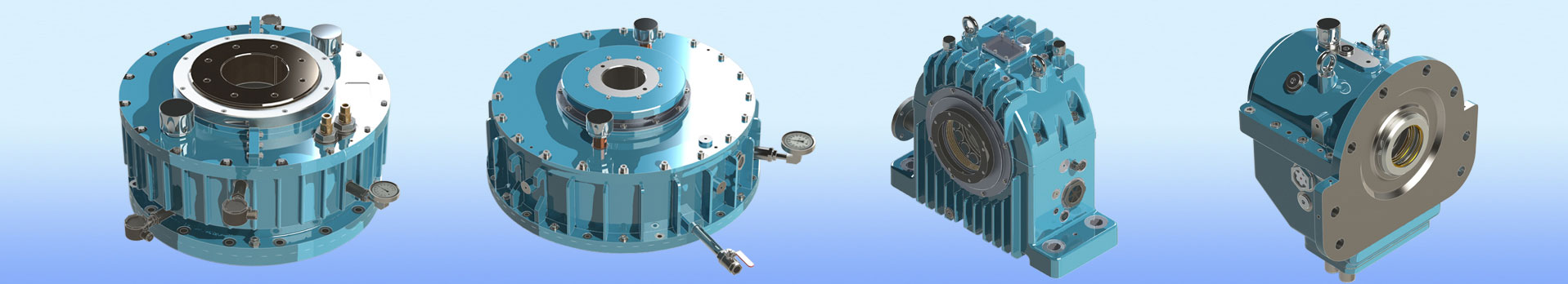
ZHEJIANG BHS JOURNAL BEARING CO.,LTD. located in FengXian District of ZheJiang, the company's brand "BHS", is a professional tilting pad thrust bearings manufacturers and Tilting pad bearings factory...
According to the data that the rotor needs to be adjusted, the thickness of the lower half of the pad adjustment gasket needs to be adjusted.
For example: if you want to raise the rotor by 0.20mm, you must replace the left and right adjustment shims in the lower half with shims that are 0.20×0.7 = 0.14mm thicker than the original shims (by processing spare shims); if you want to move the rotor to the right Shift 0.20mm, then grind off the lower right washer 0.20×0.7 = 0.14mm, and then replace the lower left adjusting washer with a gasket that is 0.14mm thicker than the gasket (by machining a spare gasket).
After the thickness of the lower half tile adjustment shim is changed, in order to ensure that the bearing clearance remains unchanged, the diagonal position of the upper half tile adjustment shim should be changed accordingly.
For example, the thickness of the adjusting shim of #3 tile is increased by 0.14mm, and the adjusting shim of #1 tile should be thinned by 0.14mm accordingly (as shown in the figure).
Bearing clearance value measurement
For fixed-pad bearings, pressure lead wires or feeler gauges can be used for measurement, and for tilting-pad bearings, the following methods can be used for measurement. Measure the dimensions of each part of the rotor and bearing separately, and make corresponding records. The specific steps are as follows:
Measure the diameter of the rotor journal:
Select multiple locations for measurement, take the average value, and compare it with the design value on the drawing, which should match.
Measure the inner diameter of the bearing bush:
The inner diameter of the bearing pad is calculated by subtracting the total thickness of the pad, the pad and its adjusting pad from the size of the inner hole of the shell.
①Measure the inner hole of the shell:
The upper and lower halves of the shell are combined with bolts, and the bolts are tightened according to the specified torque, and then measure the inner diameters of #1, #3 spacers and #2, #4 spacers.
②Measure the thickness of #1, #2, #3, #4 tiles and their spacers and adjusting spacer assembly respectively.
as shown in picture 2. The pad can be buckled on the mandrel (the diameter of the mandrel is greater than or equal to the rotor journal, and less than or equal to the inner diameter of the pad), and measured with a standard sample block and a watch. The outer surface of the spacer is a double cylindrical surface, so its highest point must be measured when measuring.
(3) Calculate the bearing clearance based on the measured data. The bearing clearance is equal to the shell inner diameter minus the thickness of the pad assembly and then the rotor journal.
ZHEJIANG BHS JOURNAL BEARING CO.,LTD. located in FengXian District of ZheJiang, the company's brand "BHS", is a professional tilting pad thrust bearings manufacturers and Tilting pad bearings factory...
Copyright © 2017 ZHEJIANG BHS JOURNAL BEARING CO.,LTD. All Right Reserved. China Tilting Pad Journal Bearings Manufacturers
