
 Tel:+86-575 -87957662
 Email:

 English
 中文简体
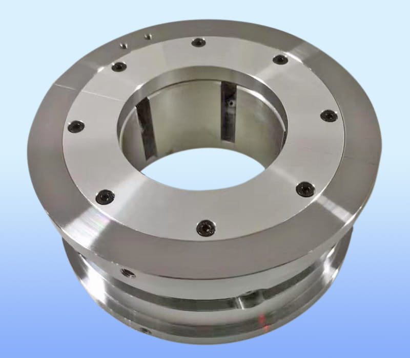
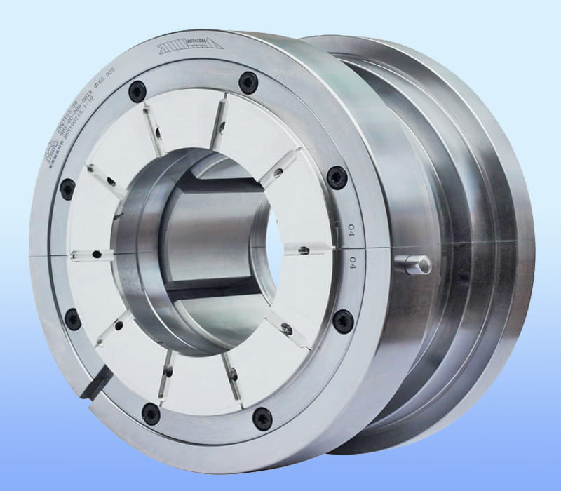
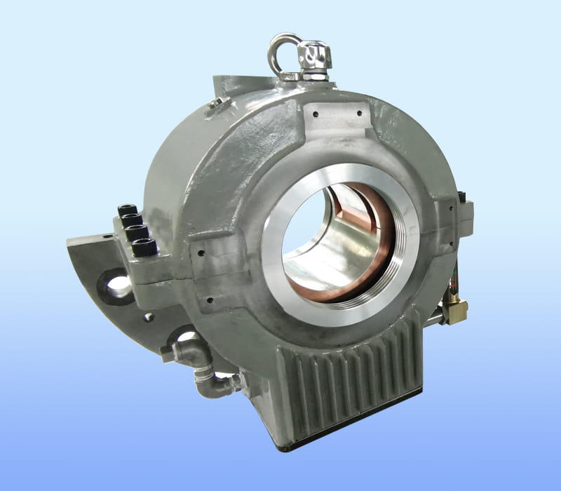
ZHEJIANG BHS JOURNAL BEARING CO.,LTD. located in FengXian District of ZheJiang, the company's brand "BHS", is a professional tilting pad thrust bearings manufacturers and Tilting pad bearings factory...

Ask any rotor dynamics engineer what limits a fast machine, and the answer often starts at the bearings. Once a rotor climbs past 20,000 rpm, the bearing must maintain a thin, stable film of oil while the surface beneath it moves at tens of meters per second. Choosing the right high speed motor journal bearings is therefore less a catalogue exercise and more a balance between stiffness, damping, heat removal and manufacturability.
This guide walks through the decisions that matter most. It explains how the bearing works, which specifications belong on a datasheet, how pad materials and pivot geometry change behaviour, and how insulation and temperature monitoring protect the machine over its service life. The goal is practical: after reading, you should be able to write a selection brief that a bearing engineering team can quote against without guesswork.
At low speed, a bearing mainly supports static weight and a modest unbalance force. As speed rises, the dynamic forces grow rapidly, so a small mass imbalance that was harmless at 3,000 rpm can become a serious vibration source at 25,000 rpm. The bearing has to absorb this energy without allowing the shaft to drift away from its centre.
Unbalance, misalignment and gear mesh all generate forces that rotate with the shaft. The bearing sees these as alternating loads whose direction changes thousands of times per minute. A design that looks adequate on a static load check may still fail in service, because its stiffness and damping are too low to suppress the resonance crossed during start-up and coast-down.
Surface speed depends on both journal diameter and rotational speed. A 150 mm journal turning at 20,000 rpm produces a surface speed well above 100 m/s. At these speeds, viscous shear heating in the oil film becomes the dominant heat source, and the bearing must carry that heat away fast enough to prevent oil breakdown and pad overheating. Heat removal, not only load capacity, often decides whether a design succeeds.
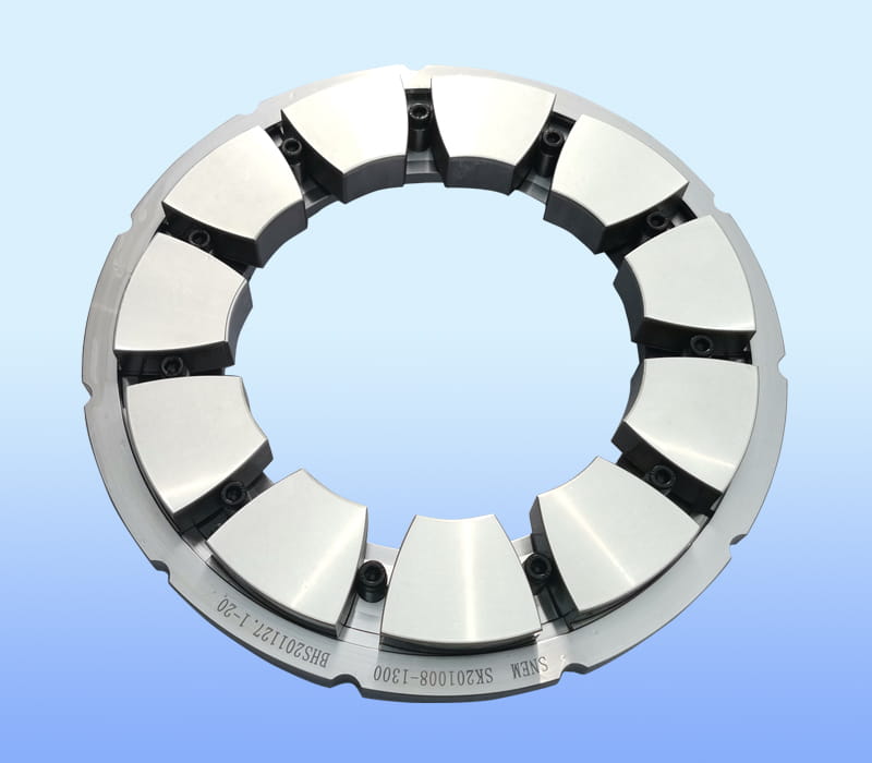
A tilting pad journal bearing is built around a set of independent pads arranged around the shaft. Each pad is free to tilt on its pivot, so a converging oil wedge forms under every pad as the shaft rotates. Because each pad finds its own angle, the bearing copes with changes in load and speed far better than a fixed-geometry sleeve.
Oil is dragged into the narrowing gap between the shaft and each pad, building pressure that lifts the journal off the surface. Each pad settles at an equilibrium angle, and the film stiffness and damping depend directly on that angle. This self-adjusting behaviour is the main reason tilting pad designs are preferred for rotors that must remain stable across a wide speed range.
A complete datasheet should state the physical envelope, the speed window and the mechanical limits before any discussion of price. The figures below represent a typical range for this class of bearing.
| Parameter | Typical range |
|---|---|
| Bearing bore diameter | 45 to 250 mm |
| Operating speed | 5,000 to 32,000 rpm |
| Maximum surface speed | 120 m/s |
| Average bearing pressure | 2.6 MPa |
| Pad count | 4 or 5 pads |
| Pivot offset ratio | 0.50, 0.55 or 0.60 |
Field experience shows how the same bearing family scales across very different machines. Representative installations include the following.
Most projects end up combining a few standard options. Common choices include:
Fixed thrust padsTilting pad thrustRTD sensorPTFE insulationLine pivotSpherical pivot
When a project requires a non-standard bore or pivot arrangement, the same datasheet fields listed above are what a design team needs to propose a suitable solution for high speed motor tilting pad bearings.
The material pairing decides the upper temperature a pad can tolerate, how the bearing behaves during run-in, and how it survives a stop when residual heat soaks into the housing. There is no single best choice, only a choice that fits the duty cycle.
The pivot position determines how each pad moves under load, which in turn controls film thickness, temperature distribution and the dynamic stiffness of the whole bearing. Pivot choice is therefore one of the most consequential design decisions.
Pads pivoted at the centre behave symmetrically, which makes them suitable for machines that must turn in either direction. Assembly is straightforward and spare-part inventories are easier to manage, which is why centre pivot pads are often the standard configuration when surface speed stays moderate.
When surface speed exceeds roughly 60 m/s, an offset pivot placed toward the leading edge helps build a stronger converging film. The result is lower pad temperature and a more favourable balance of stiffness and damping, which helps suppress whirl. Offset pivots are generally unidirectional, so the rotation direction must be fixed and stated clearly in the brief.
Motors driven by variable-frequency drives or built with uneven magnetic paths can develop shaft voltages. If the resulting current discharges through the bearing, it pits the running surface and shortens life quickly. Protecting the bearing against this is a design requirement, not an optional extra, whenever the drive architecture makes shaft currents likely.
A dielectric coating on one side of the bearing interrupts the current path while leaving the sliding surface unaffected. The coating must withstand the oil temperature, the assembly process and the mechanical loads without cracking or delaminating. Specifying the insulation requirement early avoids costly rework when the drive system is commissioned.
Resistance temperature detectors placed close to the loaded pad give a direct view of the thermal condition inside the bearing. Trending the reading over time reveals a developing problem long before a trip threshold is reached. Monitoring is also valuable during standstill, because residual heat in the housing can raise the temperature of the oil film while the machine is stopped, and an early warning helps operators decide when a restart is safe.
Most bearing failures in high-speed machines trace back to a mismatch between speed, load and pad geometry rather than to a single defective component. The table below summarises the symptoms that appear most often and the design responses that usually help.
| Symptom | Likely cause | Practical response |
|---|---|---|
| Excessive temperature rise | Low film thickness or poor heat removal | Review pivot offset, pad material and oil flow |
| Subsynchronous vibration | Oil whirl from insufficient damping | Adjust pivot offset and bearing clearance |
| Temperature rise after stop | Heat soak from residual housing heat | Select materials suited to standstill heat and monitor restart |
| Pitting on running surface | Shaft current discharge | Add a dielectric coating and verify grounding |
Addressing a symptom in isolation often moves the problem elsewhere. A change in pivot offset, for example, alters stiffness and may shift a vibration problem to a different speed range, so each change should be checked against the full operating envelope.
Tilting pad designs appear in a wide range of rotating equipment where stability at speed is the central concern. Engineers who work on compressor and expander rotors will recognise the same questions, and many readers researching tilting pad journal bearings for these machines follow the selection path set out in this guide.
A well-prepared brief shortens the design cycle and reduces the number of clarification rounds. The following list covers the information a bearing engineering team usually needs.
A brief containing these items generally produces a faster and more accurate technical proposal than a request that lists only the bore and speed.
Standard designs commonly operate from about 5,000 rpm up to around 32,000 rpm. The exact limit depends on bore size, surface speed, lubrication and pad geometry, so the final figure should be confirmed against the full operating envelope.
Yes. Centre pivot and offset pivot arrangements are both available, and the offset ratio can be adjusted within a practical range to suit the surface speed and the desired stiffness and damping characteristics.
An insulating coating interrupts shaft current paths that can discharge through the bearing and damage the running surface. It is especially important in motors driven by frequency converters or built with asymmetric magnetic circuits.
Copper-chromium backing with babbitt overlay, steel backing with copper-lead lining, and babbitt options that meet European chemical restriction rules are common choices. Each suits a different temperature, load and documentation requirement.
Embedded RTD sensors can be supplied so that operators can trend the pad temperature over time. Monitoring helps detect developing problems and supports safe restart decisions after a stop.
Centre pivot pads support rotation in either direction and are simpler to maintain. Offset pivot pads are generally used above about 60 m/s and unidirectional rotation, where they can lower pad temperature and improve damping.
High speed motor journal bearings succeed when speed, load, heat removal and rotor dynamics are considered together rather than one at a time. Bore size, speed window, load direction, pad material, pivot geometry, insulation and temperature monitoring form the core of any sound selection.
Engineers who document these parameters clearly at the outset gain the most from the design process, because the resulting bearing matches the machine it has to support. Preparing a complete brief is the most effective first step toward a reliable installation.

ZHEJIANG BHS JOURNAL BEARING CO.,LTD. located in FengXian District of ZheJiang, the company's brand "BHS", is a professional tilting pad thrust bearings manufacturers and Tilting pad bearings factory...
Copyright © 2017 ZHEJIANG BHS JOURNAL BEARING CO.,LTD. All Right Reserved. China Tilting Pad Journal Bearings Manufacturers
