
 Tel:+86-575 -87957662
 Email:

 English
 中文简体
ZHEJIANG BHS JOURNAL BEARING CO.,LTD. located in FengXian District of ZheJiang, the company's brand "BHS", is a professional tilting pad thrust bearings manufacturers and Tilting pad bearings factory...

A pump running at several thousand revolutions per minute while carrying the hydraulic forces of many impellers depends on one component that rarely receives attention until it fails: the bearing. In a multi-stage pump, the rotor carries a stack of stages, and each stage adds load. The multi-stage pump plain bearings beside the rotor must absorb those forces, keep the shaft centered, and carry away the heat generated by friction, all while the fluid conditions around them keep changing.
This guide explains how the bearing works, which specifications matter most, how materials and cooling choices affect service life, and what to check before you select or replace a unit. The goal is practical: fewer surprises during commissioning and longer intervals between overhauls.
In a multi-stage pump the rotor is long and slender, and the impellers are arranged in series on one shaft. The pressure developed by each stage pushes the shaft sideways and along its axis. A plain bearing, sometimes called a sleeve or journal bearing, supports the radial part of that load through a thin film of oil that forms between the rotating journal and the stationary lining. Unlike rolling element bearings, it contains no balls or rollers that can fatigue, so its life depends on three things: the stability of the oil film, the thermal condition of the lining, and the cleanliness of the lubricant.
The oil film is generated by the shaft rotation itself, which means bearing behavior changes with speed, load and oil temperature. At low speed the film is thin, and metal contact can occur during start-up and coast-down. At high speed the film thickens and stabilizes, but friction heat rises quickly. A well designed bearing keeps the film intact across the full operating envelope, which is why experienced engineers treat the bearing as a system rather than a single part.
The cross-section below shows how these functions map onto the physical components of a typical water-cooled assembly.
Before comparing suppliers or drawings, it helps to agree on a common set of operating parameters. The table below lists the variables that most often determine whether a bearing runs cool and stable, along with the engineering reason each one matters.
| Parameter | Typical range | Why it matters |
|---|---|---|
| Journal diameter | 75 to 350 mm | Sets bearing area and sliding velocity |
| Rotational speed | 750 to 8,500 rpm | Governs film thickness and heat generation |
| Radial load | Set by stage count and head | Determines bush width and lining choice |
| Lubrication | Forced oil supply | Maintains the film at start-up and under swings |
| Cooling | Water-cooled housing | Limits bearing metal temperature rise |
| Lining | Babbitt on steel or copper base | Provides conformability and embeddability |
These ranges describe common configurations rather than universal limits. The exact values depend on pump duty, the number of stages and the operating code adopted by the plant.
Two parameters deserve particular attention. Sliding velocity, which depends on both diameter and speed, determines how readily a stable film forms. Radial load per unit of bearing area determines how much pressure the lining must tolerate. When either value is pushed toward its limit, small errors in clearance or oil supply become far more consequential.
The lining is the part of the bearing that actually meets the shaft, so its metallurgy is central to performance. Most industrial plain bearings use babbitt, a soft white metal alloy with tin or lead as the main element. Babbitt is valued for its ability to conform to small misalignments, to embed hard particles that would otherwise score the journal, and to reduce damage if the film briefly breaks down. The softness that makes it forgiving also means it cannot carry extreme loads without a strong backing.
The base provides the structural strength that prevents the soft lining from deforming under load. Chromium molybdenum alloy steel is widely used for its toughness and fatigue resistance. Copper-chromium alloys offer higher thermal conductivity, which helps remove heat quickly from the bush, but they cost more and are usually reserved for designs where thermal management is the limiting factor. Both bases must be bonded to the babbitt through a clean, defect-free joint, because a weak bond is one of the most common causes of early lining loss.
Shaft alignment in a multi-stage pump is never perfect. Thermal growth, foundation settlement and coupling offsets all introduce small angular and parallel errors. A rigid bush that ignores these errors concentrates load on one edge, which raises local temperature and can wipe the lining. For this reason, many designs borrow the self-aligning principle used in a self-balance tilting pad thrust bearing, where individual pads pivot to form a converging oil wedge and share the load evenly.
A self-aligning sleeve has a spherical or pivoting seat that allows the bush to tilt slightly with the journal. The center of rotation is positioned so that the film remains convergent across a range of angles. Designers typically verify three things: that the contact pattern is uniform after assembly, that clearances remain within tolerance at operating temperature, and that the seat does not bind when the rotor expands. A bearing that looks perfect on the drawing can still fail if these interactions are ignored.
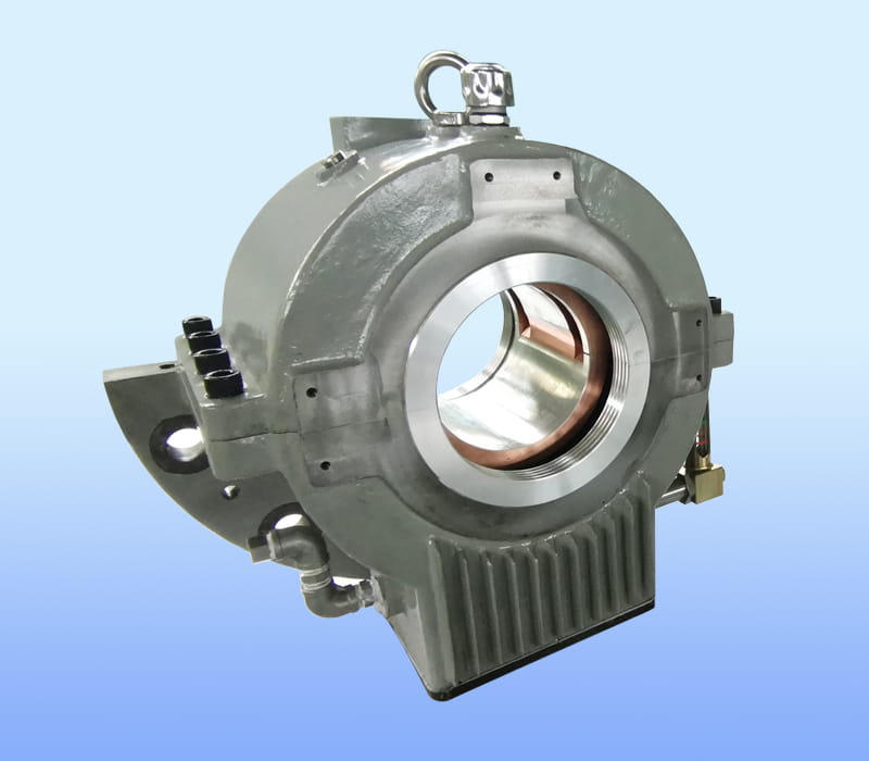
The housing carries a coil or jacket through which cooling water flows. Its job is to remove heat that the oil alone cannot dissipate, especially at high speed or in hot climates. Four details decide whether the cooling system performs as intended:
Forced lubrication means oil is delivered to the bearing by a dedicated pump at controlled pressure and flow, instead of relying on the shaft to draw oil in by itself. That independence matters during start-up, when the shaft has not yet built speed, and during load changes, when the film must recover quickly. A forced system also gives operators direct control over oil temperature, one of the most sensitive variables in bearing performance.
The loop shown above is simple in concept but demands care in execution. Each component must be sized for worst-case flow, and the cooler must be able to bring oil back to its design temperature after a full load step.
Particulate contamination is one of the leading causes of bearing wear. Hard particles trapped in the film scratch the babbitt surface and gradually open clearances. Industrial oil systems typically use filtration in the range of around 10 to 25 microns, with differential pressure monitoring across the filter so that clogging is detected before it starves the bearing. Water ingress and oxidation products are equally damaging, which is why sampling and periodic oil analysis should be part of any maintenance plan.
Good monitoring turns bearing health from guesswork into a measurable trend. The table below summarizes the points most often instrumented and the response each reading should trigger.
| Monitoring point | Purpose | Typical response |
|---|---|---|
| Bearing metal temperature | Detects overheating of the lining | Alarm, then controlled trip if rising |
| Oil inlet temperature | Checks cooler performance | Adjust cooling flow or inspect cooler |
| Oil outlet temperature | Shows heat pickup in the bearing | Investigate flow loss or excess load |
| Housing vibration | Reveals instability or clearance growth | Schedule inspection and compare trend |
Trend analysis is more valuable than any single reading. A steady rise of a few degrees over several weeks, with no change in load, is often an early sign of fouling in the cooler or a developing clearance problem.
The same bearing principles apply across many high-energy rotating machines, but certain pump duties make plain bearings the natural choice. High power density, long continuous operation and the need for predictable damping all favor sleeve designs. Typical applications include:
Plants that run several identical pump trains often standardize on multi-stage pump journal bearings so that spare inventory can be shared across units and maintenance crews work with a single design. Standardization also simplifies the qualification of a replacement if the original supplier is no longer available.
The same design logic transfers to compressors, gearboxes and steam turbine auxiliaries, where high speed and heavy radial load make sleeve bearings a sound option.
A clear specification prevents most disputes between buyers and suppliers. Before issuing a request, collect the following information:
Including the failure history of the existing bearing, if one exists, is extremely helpful. A supplier who knows the mode of failure can recommend a design change rather than a like-for-like copy.
Most bearing failures are not sudden. They develop over time and leave recognizable signatures. The table below links frequent symptoms to their typical causes and the preventive action that addresses each one.
| Symptom | Likely cause | Preventive action |
|---|---|---|
| Gradual temperature rise | Cooler fouling or reduced water flow | Clean the cooler and verify water flow |
| Babbitt smearing | Start-up without adequate oil pressure | Interlock start with an oil pressure permissive |
| Scoring on the journal | Contaminated oil or hard particles | Improve filtration and sampling |
| Lining cracking or flaking | Poor bond or fatigue from overload | Verify bond quality and review load |
| Rising vibration amplitude | Clearance growth or misalignment | Check clearance and alignment records |
Many of these failures share a root cause that is easy to miss: the oil system was commissioned to a flow target but never checked under real start-up and shutdown conditions. Including those transients in the acceptance test catches problems while they are still inexpensive to fix.
Quality in a plain bearing is largely invisible once the unit is assembled, which is why verification has to happen step by step. A disciplined inspection plan usually covers the following areas:
Acceptance testing should reproduce the expected operating sequence. A bearing that runs smoothly at steady speed may still show problems during rapid acceleration or when oil temperature is at its lower limit, so the test program should include those cases.
Not every project starts with a clean specification. Older plants often lack original drawings, or the pump has been modified over the years. In these situations, the most reliable approach is a structured reverse engineering process. Measurements of the shaft journal, the existing bush and the housing interface establish the baseline. The operating history, including temperature trends and past failures, then guides the choice of lining, cooling arrangement and lubrication details.
A capable supplier will not simply copy the old part. Instead, it will propose a design review that compares the original geometry with current engineering practice, identifies risks such as undersized oil galleries or weak bond areas, and recommends a trial fit before full production. This process protects both the schedule and the plant's confidence in the replacement.
Engineers often find that the most valuable input for a retrofit is not a drawing but a record of what happened to the old bearing and when.
They support radial loads and stabilize the rotor of multi-stage centrifugal pumps, especially in high-speed, high-pressure duties such as boiler feed, process and auxiliary service.
Tin-based babbitt is the most common choice because it offers good conformability, low friction and tolerance to brief lubrication disruptions, while the steel or copper base provides structural strength.
Cooling is typically provided by a water-cooled housing combined with a forced oil circuit that carries heat away from the lining. Cooling water temperature and flow are controlled to keep bearing metal within its design range.
Yes. Journal diameter, lining chemistry, housing geometry and lubrication arrangement can all be adapted, provided the design is reviewed against operating data and the shaft is measured accurately.
Forced lubrication with a clean, specified oil is typical, supplied at controlled pressure and temperature. Filtration and periodic oil analysis are essential to long service life.
Sliding velocity, lining material, film stability, cooling capacity and running clearance all influence the achievable speed. Published operating envelopes should be treated as starting points and confirmed against the actual duty.
Multi-stage pump plain bearings reward careful engineering. Their performance depends on the interaction of geometry, lining metallurgy, lubrication and cooling, and each variable influences the others. Plants that treat the bearing as a system, monitor its thermal and vibration trends, and specify replacements with complete operating data tend to see longer overhaul intervals and fewer unplanned stops.
If you are planning a new design or a replacement, start by assembling the operating data listed in the selection checklist. Sharing that information with a qualified supplier early in the process allows a practical recommendation and a clearer quotation.

ZHEJIANG BHS JOURNAL BEARING CO.,LTD. located in FengXian District of ZheJiang, the company's brand "BHS", is a professional tilting pad thrust bearings manufacturers and Tilting pad bearings factory...
Copyright © 2017 ZHEJIANG BHS JOURNAL BEARING CO.,LTD. All Right Reserved. China Tilting Pad Journal Bearings Manufacturers
