
 Tel:+86-575 -87957662
 Email:
 English
 中文简体
中文简体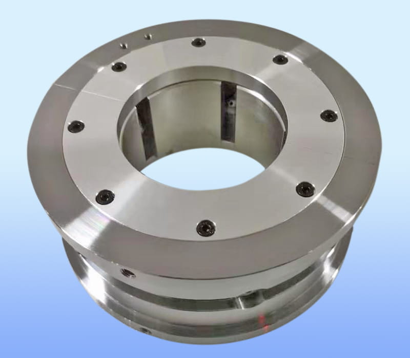
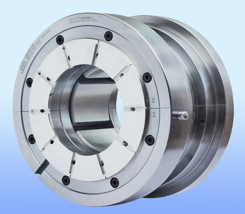
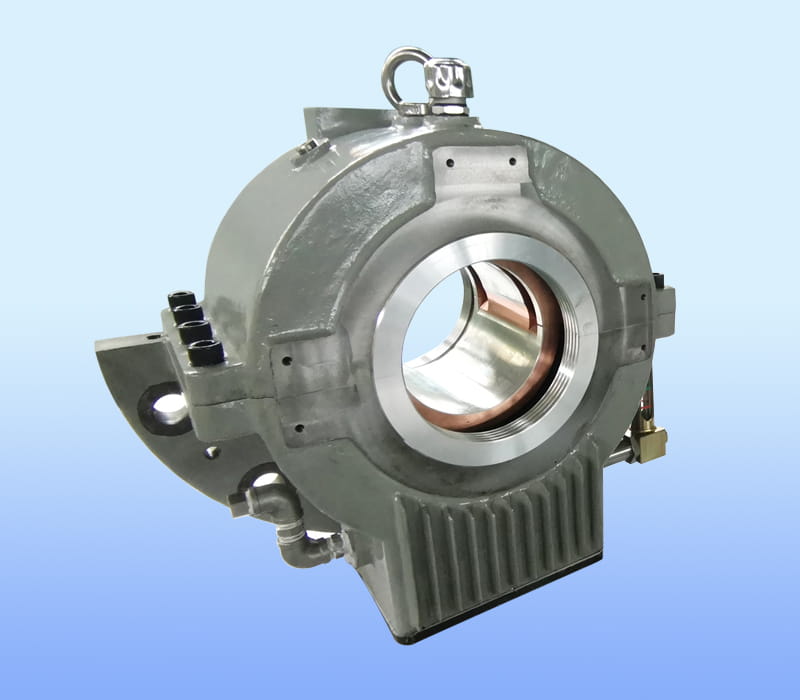
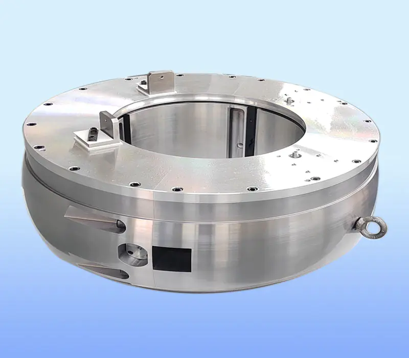
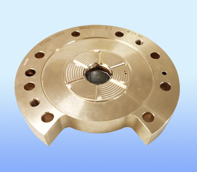
ZHEJIANG BHS JOURNAL BEARING CO.,LTD. located in FengXian District of ZheJiang, the company's brand "BHS", is a professional tilting pad thrust bearings manufacturers and Tilting pad bearings factory...

Choosing the right pump thrust pad bearings is less about buying a part and more about matching a hydrodynamic system to the real operating conditions of a machine. Pad count, babbitt quality, oil supply, collar finish and clearance all interact. When these choices are made well, the thrust bearing disappears from the maintenance log. When they are made poorly, the result is vibration, overheating and unplanned shutdowns.
This guide explains how tilting pad designs carry load, which specifications deserve the most attention, where these bearings are used, how to work through a selection step by step, and what to check when something goes wrong. The goal is practical clarity for engineers, maintenance managers and project teams who need to make sound decisions with limited time.
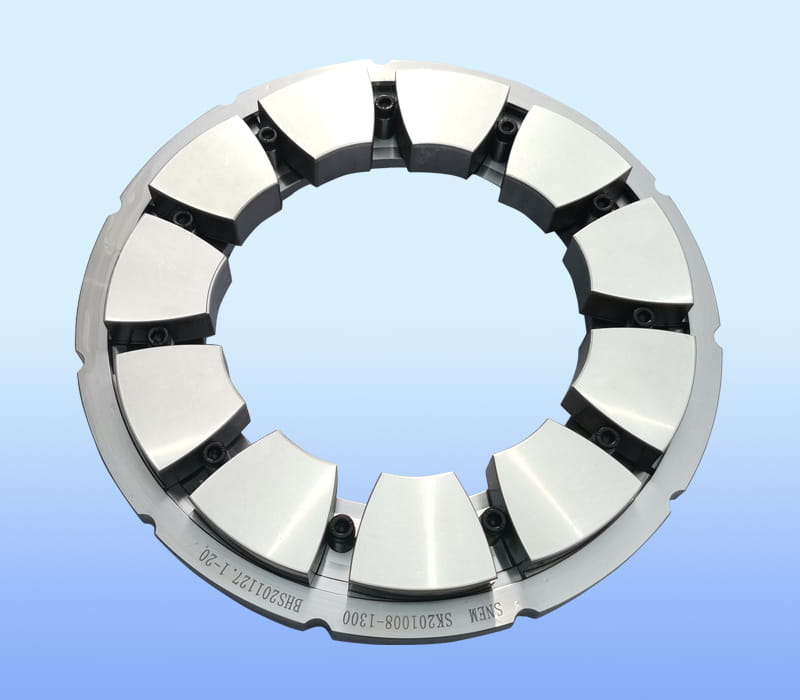
A thrust bearing has one main job: hold the rotor in its correct axial position while it transmits force from impellers and balance components into the housing. In a tilting pad arrangement, that job is done by a ring of individual pads that sit against a collar fixed to the shaft. Between the collar and each pad, a thin film of oil is pulled into a converging wedge as the collar rotates. Pressure in that film supports the load without metal-to-metal contact.
The process repeats continuously during operation. Each step depends on the one before it, which is why small changes in oil supply or clearance can have a large effect on bearing behavior.
Two families of tilting pad layouts are common. In equalizing designs, leveling links connect pads so that they share load through a mechanical balance. In a non-equalizing thrust bearing, each pad carries its own share of the load and adjusts independently on its pivot. The table below summarizes the practical differences that engineers usually weigh during selection.
| Feature | Equalizing design | Non-equalizing design |
|---|---|---|
| Load sharing | Shared through leveling links | Each pad self-adjusts on its pivot |
| Component count | Higher, with more linkage parts | Lower, with a more compact body |
| Oil feed arrangement | More complex routing | Simpler routing near each pad |
| Tolerance to uneven load | Moderate | Generally higher |
Specification sheets for thrust bearings can look dense, but only a few values drive most decisions. Collar size, rotational speed and maximum axial thrust set the basic envelope. Pad count and material then determine how that envelope is delivered in service. The ranges below reflect the typical scope seen in industrial centrifugal pump applications.
| Parameter | Typical range | Why it matters |
|---|---|---|
| Collar diameter | About 3 to 36 inches | Sets pad size and available bearing area |
| Pad count | 4 to 14 pads | Affects load sharing and film stability |
| Rotational speed | 1,000 to 8,500 rpm | Governs film thickness and heat generation |
| Linear speed at collar edge | Up to about 120 m/s | Influences oil film behavior and wear |
| Axial thrust capacity | Up to about 150 tons per bearing | Determines whether the design has margin |
The pad itself is usually made of a strong steel base that resists deformation under load. Alloy steel grades are widely used when high strength is needed, while copper-based alloys are chosen when better heat conduction is valuable. The working surface is typically a tin-based babbitt lining. Babbitt is soft enough to embed small debris and conform to minor misalignment, which protects the harder collar during start-up and shutdown.
Thrust pad designs appear wherever a pump generates significant axial force and needs stable, long-term support. The demands differ from one application to another, so the selection logic should reflect the process context rather than a generic catalog number.
Feed water pumps in power and process plants operate at high pressure and often at high speed. They experience frequent thermal cycling during start-up and load changes. Bearings in this service must tolerate temperature swings without losing film stability, and maintenance teams usually expect long intervals between inspections.
In nuclear-grade service, documentation and traceability are as important as mechanical performance. Materials, dimensions and test records must be fully recorded, and the design must satisfy strict quality requirements. Selection in this area often begins with the qualification standards that apply to the plant rather than with the pump curve alone.
Multistage pumps, including split-casing configurations commonly referred to by designations such as BB3 and BB5, stack impellers in series. Each stage adds to the total axial force, so the combined thrust can become large even when individual stages seem modest. A thrust pad bearing with sufficient pad area and a well-designed oil supply is typically required to manage this combined load safely.
Many thrust bearings are replaced rather than designed from scratch. Retrofit work depends on accurate measurements of the existing housing, collar dimensions and oil passages. Shutdown windows are often short, so a complete data package and a clear fit-check process reduce the risk of delays. In these cases, matching the original geometry while improving oil delivery can deliver a meaningful reliability gain.
Two bearings with the same nominal size can perform very differently. The details of oil delivery, pad geometry and housing fit determine how the film behaves across the full operating range. The following features are commonly used to judge the quality of a design.
Designs that combine these features tend to show lower temperature rise and more consistent behavior when load or speed changes. The advantage is especially noticeable in a tilting pad thrust bearing operating near its load limit, where small losses in film quality can quickly become a temperature problem.
A structured approach avoids the most common selection mistakes, such as choosing pad size before confirming thrust, or specifying a lining without checking the lubrication system. The flowchart below shows a practical order of decisions, followed by notes on what each step should cover.
When a retrofit is involved, add one more check: compare the new bearing envelope with the existing housing and oil passages. Even a small difference in thickness or port location can cause fit or flow problems that are expensive to fix after installation.
Thrust bearing problems rarely appear without warning. Temperature trends, vibration spectra and oil condition usually show changes long before failure. Recognizing these patterns early allows planned intervention rather than emergency repair.
When axial load is not shared evenly across pads, one or more pads can carry more force than the design intended. This produces an unstable film and can show up as elevated vibration at running speed or at harmonics. Checking rotor balance, housing bolt torque and axial clearance is usually the first step.
A sustained rise in pad temperature often points to restricted oil flow, incorrect clearance or excessive load. Comparing readings from individual pads is more informative than watching only the average, because a single hot pad can reveal a localized feed problem.
Babbitt surfaces can show scoring, smearing or pitting. These marks usually trace back to debris in the oil, a film that is too thin during start-up or stop, or contact caused by misalignment. Inspecting oil filters and reviewing start-up procedures often reveals the root cause.
| Symptom | Likely cause | First action |
|---|---|---|
| Temperature rising on one pad | Restricted oil feed or misaligned pad | Check oil flow and pad clearance |
| Periodic vibration at running speed | Rotor imbalance or loose housing | Verify balance and fastener torque |
| Pitting or smearing on babbitt | Debris, thin film or frequent start-stop stress | Inspect filters and review start-up sequence |
| Gradual rise in oil temperature | Reduced cooling or excessive friction | Check cooler performance and oil condition |
Suppliers can only recommend a sound design when they receive complete operating information. Incomplete data often leads to conservative assumptions that increase cost or lead time. A clear data package shortens the technical review and produces a more realistic proposal.
If you are evaluating options for a specific pump, gather the operating data above and share it with a supplier along with any drawings. This allows a technical review of pad geometry, lining and oil delivery before any commercial discussion begins.
Pump thrust pad bearings are hydrodynamic bearings made of a ring of tilting pads that support axial load from the rotor. A thin oil film forms between the pads and a collar on the shaft, which carries the force without direct metal contact.
The pads usually have a steel or copper-based structural body with a tin-based babbitt lining on the working face. The base material is chosen for strength and heat transfer, while the lining provides embeddability and tolerance to brief contact during start-up and shutdown.
Capacity depends on collar size, pad count, speed and oil supply. Designs in industrial service can reach several hundred thousand pounds of axial thrust, but the real limit is set by film temperature and pad loading, so the rated value should always be confirmed against the actual duty.
Yes. Custom designs are common when the pump is unusual, when a retrofit must match an existing housing, or when a project requires special materials or documentation. A drawing and complete operating data allow the supplier to confirm fit, geometry and oil flow before manufacturing begins.
Non-equalizing layouts are often chosen for feed water pumps, high-speed multistage pumps and other applications where compact size, simpler oil routing and independent pad movement are valuable. The final choice still depends on load behavior and the lubrication arrangement.
A supplier typically needs pump type, speed, normal and maximum axial thrust, existing dimensions or drawings, lubrication details and any documentation requirements. Providing these items up front allows a faster technical review and a more accurate quotation.

ZHEJIANG BHS JOURNAL BEARING CO.,LTD. located in FengXian District of ZheJiang, the company's brand "BHS", is a professional tilting pad thrust bearings manufacturers and Tilting pad bearings factory...
Copyright © 2017 ZHEJIANG BHS JOURNAL BEARING CO.,LTD. All Right Reserved. China Tilting Pad Journal Bearings Manufacturers
